Armature Winding
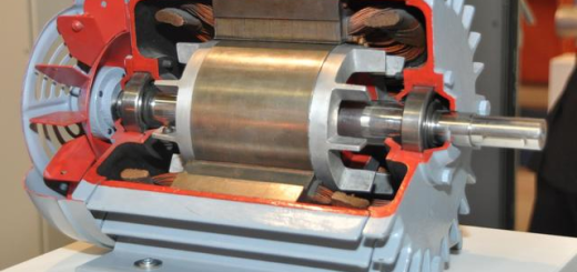
The armature winding consists of a certain number of armature coils connected according to a certain law, he is the circuit part of the DC motor, but also the induction of electric potential, electromagnetic torque for electromechanical energy conversion part. Coil with insulated round or rectangular cross-section of the wire wound, divided into upper and lower two layers embedded in the armature core groove, the upper and lower layers as well as between the coil and the armature core should be properly insulated, and pressed with groove wedge. The ends of the armature windings of large motors are usually fastened to the winding supports.
A set of coils wound and connected in the armature of a motor according to a certain pattern. It is one of the main components of the motor that realizes electromechanical energy conversion. Composition of the armature winding coil has a single turn, there are also multi-turns, each turn can also be wound by a number of parallel wires.

Armature winding design requirements: the composition of the armature winding, should be able to produce enough induction electromotive force, and allow the passage of a certain armature current, so as to produce the required electromagnetic torque and electromagnetic power, in addition, but also to save non-ferrous metals and insulation materials, simple structure, reliable operation.
Armature windings are divided into two categories: DC armature windings and AC armature windings. They are used for DC motors and AC motors respectively. Common terminology for armature winding element (coil): the winding coil is called the winding element, divided into single-turn and multi-turn. An element consists of two elements edge and termination line, element edge in the slot, can cut the line of magnetic force and produce induced electromotive force, called the “effective edge”, the termination line is placed outside the slot, does not cut the line of magnetic force, only as a connection line. One component side of each element is placed on the upper level of one slot, and the other component side is placed on the lower level of another slot. The first and the end of the element: Each element is connected to the commutator by two wires, one of which is called the first end and the other is called the end. The two ends of each element are connected to different commutator tabs, and each commutator tab is connected to two different coil ends.
Real slots: The actual slots cut in the armature of a motor are called real slots. The number of real slots is indicated by Q. Virtual slot: that is, the unit slot (the number of component edges per layer is equal to the number of virtual slots), each virtual slot of the upper and lower layers have a component edge. The number of virtual slots is denoted by Qμ. Let there are μ virtual slots in each layer of the slot, if the number of real slots is Q and the number of virtual slots is Qμ, then Qμ= μQ. pole axis: the centerline of the magnetic poles. Geometric Neutral Line: is the mechanical dividing line between the N and S poles of the main magnetic poles. Physical Neutral Line: The dividing line between the N and S poles where the magnetic field is zero is called the physical neutral line.